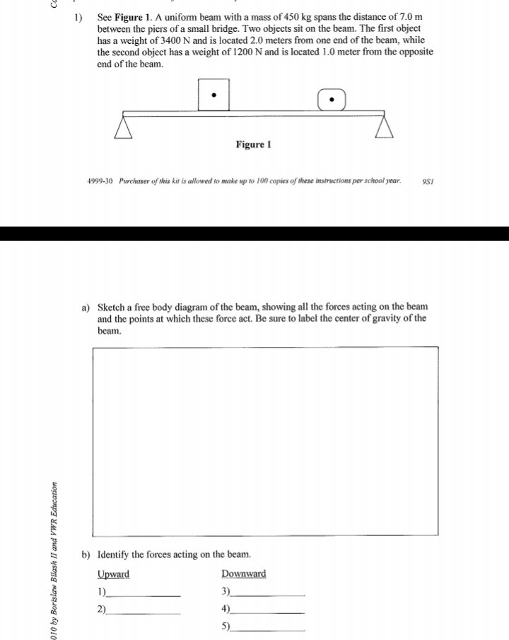
The 450-kg uniform I-beam supports the load shown. Determine the reactions at the supports. Problem 3/24 A block placed under the head of the claw hammer as shown greatly facilitates the extraction of the nail. If simply supported at both ends and 450 kg and 220 kg are total loads uniformly distributed along the beam, each end reaction (at supports) is one half of (450 + 220 = 670 kg) or 335 kg. 95 views View 1 Upvoter.
Calculate beam load and supporting forces
Online Beam Support Force Calculator
The calculator below can be used to calculate the support forces - R1 and R2 - for beams with up to 6 asymmetrically loads.
For a beam in balance loaded with weights (or other load forces) the reactions forces - R - at the supports equals the load forces -F. The force balance can be expressed as

F1 + F2 + .. + Fn = R1 + R2 (1)
where
F = force from load (N, lbf)
R = force from support (N, lbf)
In addition for a beam in balance the algebraic sum of moments equals zero. The moment balance can be expressed as
F1 af1 + F2 af2 + .. + Fn afn = R ar1 + R ar2 (2)
where
a = the distance from the force to a common reference - usually the distance to one of the supports (m, ft)
Example - A beam with two symmetrical loads
A 10 m long beam with two supports is loaded with two equal and symmetrical loads F1 and F2 , each 500 kg. The support forces F3 and F4 can be calculated
(500 kg) (9.81 m/s2) + (500 kg) (9.81 m/s2) = R1 + R2
=>
R1 + R2 = 9810 N
= 9.8 kN
Note! Load due to the weight of a mass - m - is mg Newton's - where g = 9.81 m/s2.
With symmetrical and equal loads the support forces also will be symmetrical and equal. Using
R1 = R2
the equation above can be simplified to
R1 = R2 = (9810 N) / 2
= 4905 N
= 4.9 kN
Related Mobile Apps from The Engineering ToolBox
- free apps for offline use on mobile devices.
Example - A beam with two not symmetrical loads
A 10 m long beam with two supports is loaded with two loads, 500 kg is located 1 m from the end (R1), and the other load of 1000 kg is located 6 m from the same end. The balance of forces can be expressed as
(500 kg) (9.81 m/s2) + (1000 kg) (9.81 m/s2) = R1 + R2
The 450 Kg Uniform I Beam Sizes
=>

R1 + R2 = 14715 N

= 14.7 kN
The algebraic sum of moments (2) can be expressed as
(500 kg) (9.81 m/s2) (1 m) + (1000 kg) (9.81 m/s2) (6 m) =?R1 (0 m) + R2 (10 m)
The 450 Kg Uniform I Beam Calculator
=>

R2 = 6377 (N)
= 6.4 kN
F3can be calculated as:
R1= (14715 N) - (6377 N)
= 8338 N
What is looping statement in c++. A loop statement allows us to execute a statement or group of statements multiple times and following is the general from of a loop statement in most of the programming languages − C programming language provides the following type of loops to handle looping requirements.
= 8.3 kN
Insert beams to your Sketchup model with the Engineering ToolBox Sketchup Extension
Related Topics
- Mechanics - Forces, acceleration, displacement, vectors, motion, momentum, energy of objects and more
- Beams and Columns - Deflection and stress, moment of inertia, section modulus and technical information of beams and columns
- Statics - Loads - force and torque, beams and columns
Related Documents
- Aluminum I-Beams - Dimensions and static properties of aluminum I-beams - Imperial units
- American Standard Beams - S Beam - American Standard Beams ASTM A6 - Imperial units
- American Standard Steel C Channels - Dimensions and static parameters of American Standard Steel C Channels
- American Wide Flange Beams - American Wide Flange Beams ASTM A6 in metric units
- American Wide Flange Beams - W Beam - Dimensions of American Wide Flange Beams ASTM A6 - Imperial units
- Beams - Fixed at Both Ends - Continuous and Point Loads - Support loads, stress and deflections
- Beams - Fixed at One End and Supported at the Other - Continuous and Point Loads - Support loads, moments and deflections
- Beams - Supported at Both Ends - Continuous and Point Loads - Support loads, stress and deflections
- British Universal Columns and Beams - Properties of British Universal Steel Columns and Beams
- Cantilever Beams - Moments and Deflections - Maximum reaction force, deflection and moment - single and uniform loads
- Continuous Beam - Moment and Reaction Support Forces - Moment and reaction support forces with distributed or point loads
- Drawbridge Elevation - Forces and Moments - Calculate elevation moment for a drawbridge or a beam
- Equilibrant - The force required to keep a system of forces in equilibrium
- HE-A Steel Beams - Properties of HE-A profiled steel beams
- HE-B Steel Beams - Properties of HE-B profiled steel beams
- HE-M Steel Beams - Properties of HE-M profile steel beams
- Normal Flange I Beams - Properties of normal flange I profile steel beams
- Square Hollow Structural Sections - HSS - Weight, cross sectional area, moments of inertia - Imperial units
- Steel Angles - Equal Legs - Dimensions and static parameters of steel angles with equal legs - imperial units
- Steel Angles - Equal Legs - Dimensions and static parameters of steel angles with equal legs - metric units
- Steel Angles with Unequal Legs - Dimensions and static parameters of steel angles with unequal legs - imperial units
- Steel Angles with Unequal Legs - Dimensions and static parameters of steel angles with unequal legs - metric units
- Steel Pipe Columns - Allowable Loads - Allowable concentric loads for steel pipe columns
- Triangle - Triangle analytical geometry
- Trusses - Common types of trusses
- Weight of Beam - Stress and Strain - Stress and deformation of a vertical beam due to it's own weight
Tag Search

F1 + F2 + .. + Fn = R1 + R2 (1)
where
F = force from load (N, lbf)
R = force from support (N, lbf)
In addition for a beam in balance the algebraic sum of moments equals zero. The moment balance can be expressed as
F1 af1 + F2 af2 + .. + Fn afn = R ar1 + R ar2 (2)
where
a = the distance from the force to a common reference - usually the distance to one of the supports (m, ft)
Example - A beam with two symmetrical loads
A 10 m long beam with two supports is loaded with two equal and symmetrical loads F1 and F2 , each 500 kg. The support forces F3 and F4 can be calculated
(500 kg) (9.81 m/s2) + (500 kg) (9.81 m/s2) = R1 + R2
=>
R1 + R2 = 9810 N
= 9.8 kN
Note! Load due to the weight of a mass - m - is mg Newton's - where g = 9.81 m/s2.
With symmetrical and equal loads the support forces also will be symmetrical and equal. Using
R1 = R2
the equation above can be simplified to
R1 = R2 = (9810 N) / 2
= 4905 N
= 4.9 kN
Related Mobile Apps from The Engineering ToolBox
- free apps for offline use on mobile devices.
Example - A beam with two not symmetrical loads
A 10 m long beam with two supports is loaded with two loads, 500 kg is located 1 m from the end (R1), and the other load of 1000 kg is located 6 m from the same end. The balance of forces can be expressed as
(500 kg) (9.81 m/s2) + (1000 kg) (9.81 m/s2) = R1 + R2
The 450 Kg Uniform I Beam Sizes
=>
R1 + R2 = 14715 N
= 14.7 kN
The algebraic sum of moments (2) can be expressed as
(500 kg) (9.81 m/s2) (1 m) + (1000 kg) (9.81 m/s2) (6 m) =?R1 (0 m) + R2 (10 m)
The 450 Kg Uniform I Beam Calculator
=>
R2 = 6377 (N)
= 6.4 kN
F3can be calculated as:
R1= (14715 N) - (6377 N)
= 8338 N
What is looping statement in c++. A loop statement allows us to execute a statement or group of statements multiple times and following is the general from of a loop statement in most of the programming languages − C programming language provides the following type of loops to handle looping requirements.
= 8.3 kN
Insert beams to your Sketchup model with the Engineering ToolBox Sketchup Extension
Related Topics
- Mechanics - Forces, acceleration, displacement, vectors, motion, momentum, energy of objects and more
- Beams and Columns - Deflection and stress, moment of inertia, section modulus and technical information of beams and columns
- Statics - Loads - force and torque, beams and columns
Related Documents
- Aluminum I-Beams - Dimensions and static properties of aluminum I-beams - Imperial units
- American Standard Beams - S Beam - American Standard Beams ASTM A6 - Imperial units
- American Standard Steel C Channels - Dimensions and static parameters of American Standard Steel C Channels
- American Wide Flange Beams - American Wide Flange Beams ASTM A6 in metric units
- American Wide Flange Beams - W Beam - Dimensions of American Wide Flange Beams ASTM A6 - Imperial units
- Beams - Fixed at Both Ends - Continuous and Point Loads - Support loads, stress and deflections
- Beams - Fixed at One End and Supported at the Other - Continuous and Point Loads - Support loads, moments and deflections
- Beams - Supported at Both Ends - Continuous and Point Loads - Support loads, stress and deflections
- British Universal Columns and Beams - Properties of British Universal Steel Columns and Beams
- Cantilever Beams - Moments and Deflections - Maximum reaction force, deflection and moment - single and uniform loads
- Continuous Beam - Moment and Reaction Support Forces - Moment and reaction support forces with distributed or point loads
- Drawbridge Elevation - Forces and Moments - Calculate elevation moment for a drawbridge or a beam
- Equilibrant - The force required to keep a system of forces in equilibrium
- HE-A Steel Beams - Properties of HE-A profiled steel beams
- HE-B Steel Beams - Properties of HE-B profiled steel beams
- HE-M Steel Beams - Properties of HE-M profile steel beams
- Normal Flange I Beams - Properties of normal flange I profile steel beams
- Square Hollow Structural Sections - HSS - Weight, cross sectional area, moments of inertia - Imperial units
- Steel Angles - Equal Legs - Dimensions and static parameters of steel angles with equal legs - imperial units
- Steel Angles - Equal Legs - Dimensions and static parameters of steel angles with equal legs - metric units
- Steel Angles with Unequal Legs - Dimensions and static parameters of steel angles with unequal legs - imperial units
- Steel Angles with Unequal Legs - Dimensions and static parameters of steel angles with unequal legs - metric units
- Steel Pipe Columns - Allowable Loads - Allowable concentric loads for steel pipe columns
- Triangle - Triangle analytical geometry
- Trusses - Common types of trusses
- Weight of Beam - Stress and Strain - Stress and deformation of a vertical beam due to it's own weight
Tag Search
- en: beams calculation load weight forces supports
- es: vigas fuerzas cálculo de peso de carga soportes
- de: Balken Rechenlast Gewichtskräfte Stützen
